Alternating Current
Overview
Alternating Current refers to electric current that varies periodically in magnitude and reverses direction with time. It is the standard form of electrical supply used in homes, industry, and national power grids.
Alternating current is important because:
- voltages can be changed efficiently using transformers
- high-voltage transmission reduces energy loss
- many generators naturally produce alternating emf
This topic builds on ideas from Current Electricity Fundamentals, DC Circuits, and Electromagnetic Induction.
Core Ideas
Alternating-current questions revolve around a small set of ideas:
- current and voltage can vary sinusoidally with time
- mean current over a full cycle is not useful for heating calculations
- rms values are the effective values used in power calculations
- transformers change voltage and current combinations, not total ideal power
- high-voltage transmission reduces cable losses because losses depend on
- rectification converts AC into unidirectional, usually pulsating, DC
Core Physical Idea
In a metal conductor, charge carriers drift back and forth as the electric field reverses direction periodically.
Although the charges do not travel continuously in one direction over long distances, energy is still transferred through the circuit.
For sinusoidal AC, current and voltage vary smoothly with time.
AC vs DC
Direct Current
- flows in one direction only
- usually has constant magnitude
- supplied by batteries or DC sources
Alternating Current
- reverses direction periodically
- magnitude changes continuously
- supplied by power stations and AC generators
Comparison Table
| Quantity | DC | AC |
|---|---|---|
| Direction | constant | reverses |
| Magnitude | constant or steady | varies |
| Frequency | 0 Hz | non-zero |
| Easily transformed? | no | yes |
Sinusoidal Alternating Current
The most common AC waveform is sinusoidal.
Current
Voltage
where:
- = instantaneous current
- = instantaneous voltage
- = peak current
- = peak voltage
- = angular frequency
- = time
Waveform Quantities
Period
Time for one complete cycle:
Frequency
Number of complete cycles per second.
Unit: hertz (Hz)
Angular Frequency
Peak Value
Maximum magnitude of current or voltage:
Peak-to-Peak Value
Difference between positive and negative peaks:
Mean Value Over One Full Cycle
For a sinusoidal AC:
The positive and negative halves cancel.
RMS Value Overview
Because mean current over a cycle is zero, it does not describe heating effect.
The useful measure is the root mean square value.
It is the value of steady DC current that would produce the same average heating effect in a resistor.
For sinusoidal AC:
See RMS and AC Power.
Heating Effect Equivalence to DC
The heating effect of current in a resistor depends on:
So negative current still gives positive power dissipation. That is why AC with zero mean current can still transfer energy and heat a resistor.
Rms values are defined so that:
- a DC current of gives the same average heating effect as the AC current
- a DC voltage of across a resistor gives the same average heating effect as the AC voltage
Power in Resistive Loads
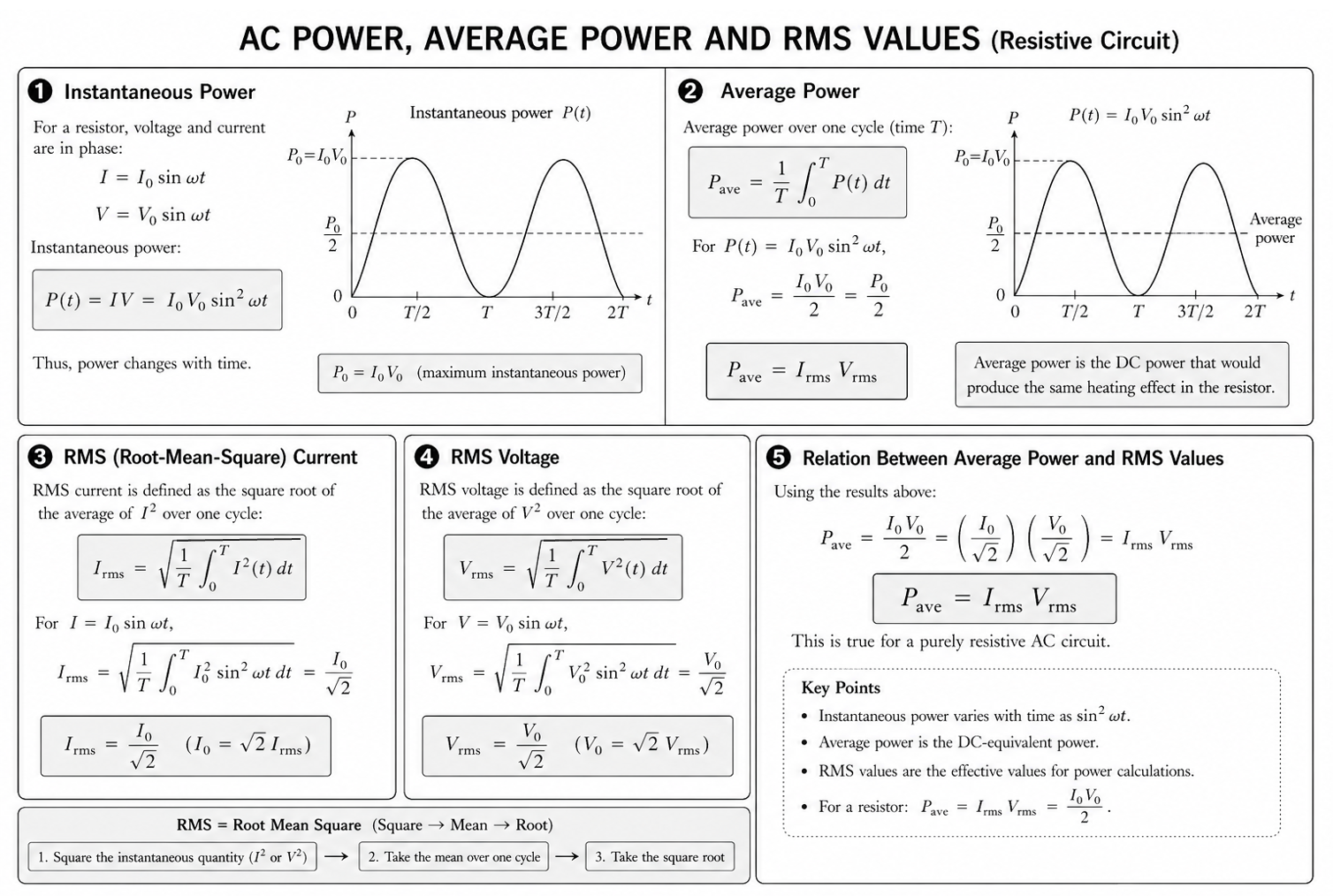
For a resistor:
Since current and voltage vary continuously, instantaneous power also varies.
For a pure resistor:
Also:
For sinusoidal AC in a resistor:
Use of RMS Values in Calculations
In practical AC questions involving resistive loads, use rms values directly in the familiar power formulas:
Do not substitute peak values into these formulas unless the question explicitly asks you to derive power from instantaneous expressions.
Transformer Overview
A transformer changes AC voltage using electromagnetic induction.
See full topic: Transformers
Figure: Ideal transformer showing primary and secondary coils linked by a common iron core.
Ideal Transformer Relations
where:
- = turns in primary and secondary coils
- = primary and secondary p.d.
- = primary and secondary current
Step-Up Transformer
- voltage increases
- current decreases
Step-Down Transformer
- voltage decreases
- current increases
Power Transmission at High Voltage
For transmission cables, the average heating loss is:
For fixed transmitted power:
Increasing transmission voltage reduces line current, so cable losses decrease greatly.
Hence power is transmitted at high voltage, then stepped down for consumers.
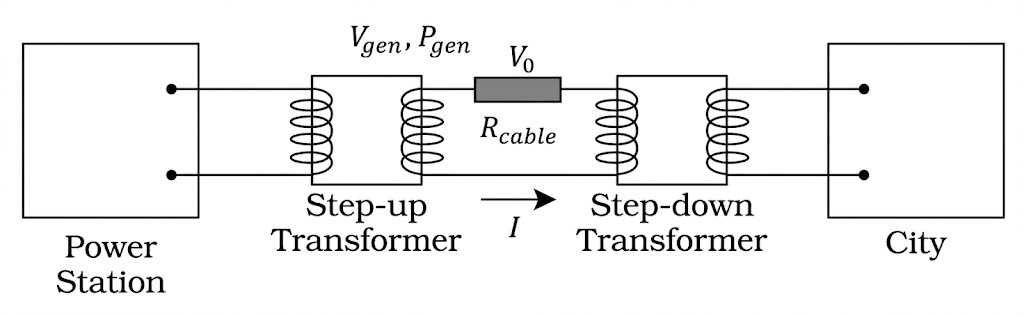
Figure: High-voltage transmission reduces current in the cables and therefore reduces power loss.
Transformer Efficiency Overview
For an ideal transformer:
So ideal input power equals ideal output power.
In practice, efficiency is less than 100% because of losses such as:
- copper loss in coils
- eddy currents
- hysteresis
- flux leakage
Detailed treatment belongs in Transformers.
Rectification Overview
Many electronic devices require DC supply.
Rectification converts AC to DC using diodes.
See Rectification.
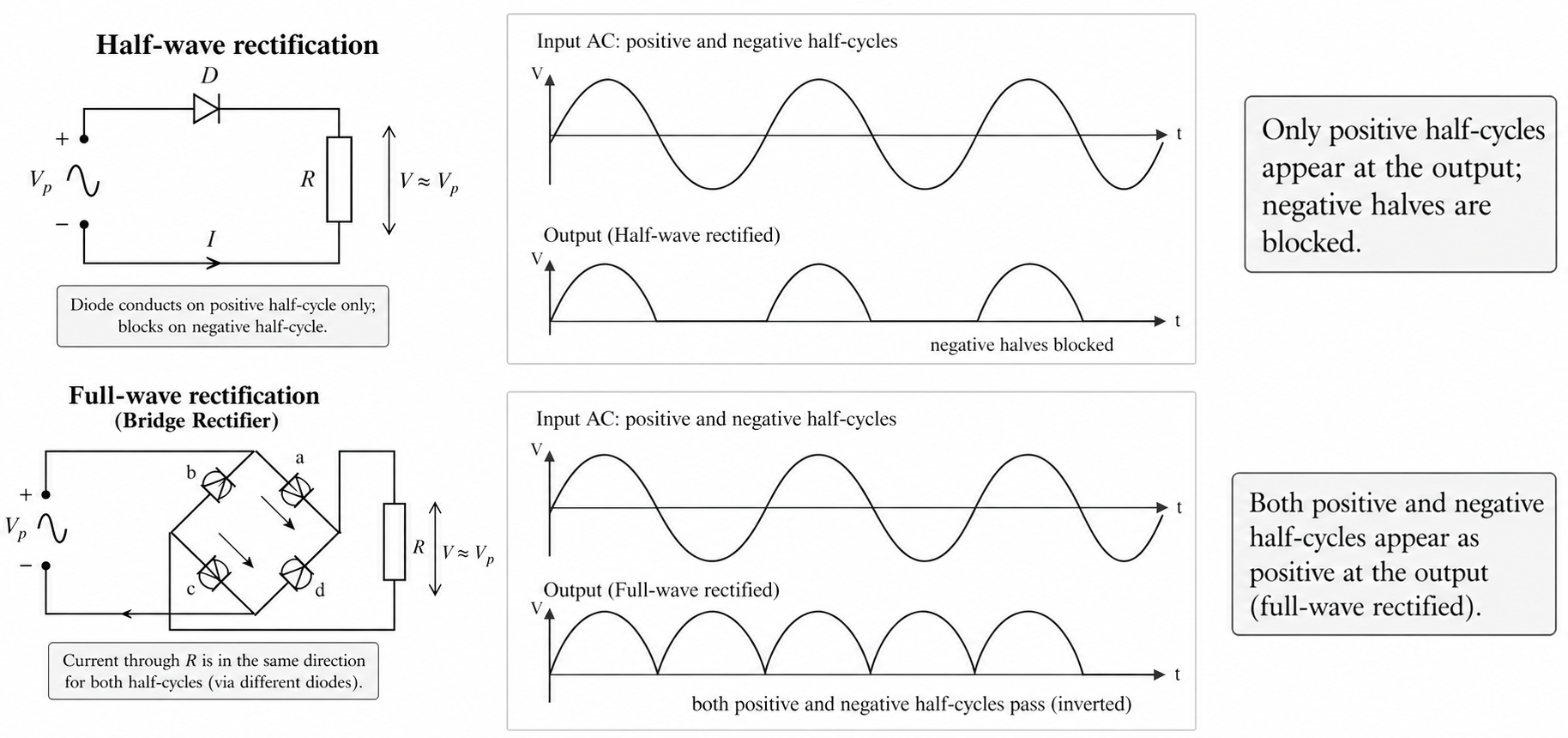
Figure: Comparison of alternating input with typical rectified outputs.
Half-Wave Rectification
- one half-cycle passes
- one half-cycle is blocked
Full-Wave Rectification
- both half-cycles are used
- output always has the same polarity across the load
The output is pulsating DC.
Pulsating DC Output
Rectified output is unidirectional, but it still varies with time.
So it is not steady DC like a battery. It is:
- one direction only
- varying in magnitude
- repeated in pulses
Household Mains Interpretation
When a wall socket is labelled 230 V or 240 V, this refers to:
It does not mean peak voltage.
Peak voltage is:
So for 240 V mains:
Singapore mains frequency is typically:
Common Exam Traps Overview
1. Confusing Peak with RMS
Use rms values in power calculations unless stated otherwise.
2. Using Mean Current for Heating
Mean current over a full cycle is zero, but mean power is not zero.
3. Wrong Transformer Current Ratio
Voltage ratio follows turns ratio, but current ratio is inverse.
4. Assuming a Transformer Increases Power
An ideal transformer changes voltage and current combination, not total ideal power.
5. Forgetting Cable Loss Depends on
Doubling current quadruples line loss.
See Alternating Current Common Exam Traps.
Exam Relevance
Alternating-current questions are often straightforward if quantities are interpreted correctly. Most lost marks come from using peak values instead of rms values, reversing the transformer current ratio, or describing rectified output as steady DC. The safest approach is to identify whether the question is about waveform description, power calculation, transformer ratios, or transmission losses before choosing formulas.
Summary
Key results:
Alternating current is central to modern electricity generation, transmission, voltage conversion, and power supply systems.